Privacy statement: Your privacy is very important to Us. Our company promises not to disclose your personal information to any external company with out your explicit permission.
![]() August 29, 2023
August 29, 2023
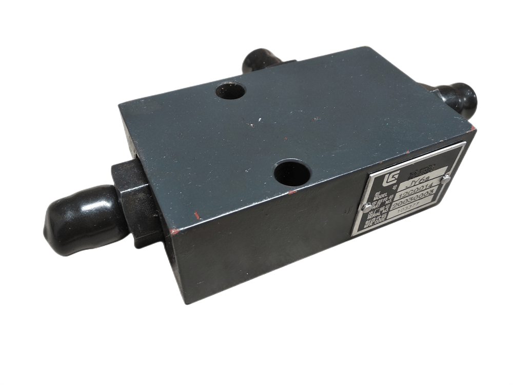
 Gear pump hydraulic circuit function analysis 1, priority flow control Regardless of gear pump speed, working pressure or branch flow size required, the value of a flow control valve can always ensure the required flow of equipment work. In this circuit, the pump output flow must be greater than or equal to the required flow of the oil circuit, secondary flow can be used for it or back to the tank. Setting a flow valve (proportional valve) will be a combination of control and hydraulic pump,Loader Hydraulic Cylinder, eliminating pipelines and eliminate external leakage, so reduce the cost. A typical application of such a gear pump circuit is the steering mechanism often found on truck cranes, which eliminates the need for a pump.Flow Amplification Valve
The above is the Function Analysis of Hydraulic Circuit in Gear Pump we have listed for you. You can submit the following form to obtain more industry information we provide for you.
You can visit our website or contact us, and we will provide the latest consultation and solutions
Send Inquiry
Most Popular
lastest New
Send Inquiry

Privacy statement: Your privacy is very important to Us. Our company promises not to disclose your personal information to any external company with out your explicit permission.

Fill in more information so that we can get in touch with you faster
Privacy statement: Your privacy is very important to Us. Our company promises not to disclose your personal information to any external company with out your explicit permission.